Inventor Tutorial: Adding Constraints and Dimensions
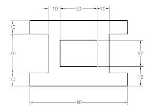
In this tutorial, you will draw the sketch shown in the image below. After drawing the sketch, you will add the required constraints and then dimension it.
 Starting a New File and Invoking the Sketching Environment Start Autodesk Inventor and then invoke the Sketching environment by selecting the sketching plane.
1. Start Autodesk Inventor by double-clicking on its shortcut icon on the desktop of your computer or by using the Start menu.
2. Choose the New tool from Quick Access Toolbar and start a new metric standard part file by using the Metric tab of the Create New File dialog box.
3. Choose the Start 2D Sketch button from the Sketch panel of the 3D Model tab; the default planes are displayed and you are prompted to select the sketching plane.
4. Choose the Home button from the ViewCube; the current orientation of the sketch plane is changed.
5. Select the XZ plane as the sketching plane from the graphics window; the Sketching environment is invoked and the XZ Plane becomes parallel to the screen.
Using the Line and Two point rectangle tools, draw the required sketch similar to the one shown in the image below.
You do not need to draw the sketch to the exact length. Use the temporary tracking option for drawing the sketch. For your reference, all lines in the sketch are numbered, see the image below.

Note that in this sketch, the display of the X and Y axes has been turned off.
Share this Technical Insight